Gyroscope and Precession: A Practical Sensor Guide
What gyroscope and precession mean
A mechanical gyroscope is a rapidly spinning body whose angular momentum points along its spin axis. Apply a torque that is not parallel to that axis and the torque changes the direction of the angular-momentum vector. The axis therefore moves around another axis instead of simply dropping in the direction of the applied force. That motion is precession.
A tilted spinning top is the familiar example. Gravity acts at its centre of mass while the support force acts at the contact point, creating a torque. A stationary top falls; a fast-spinning top can trace a cone as its axis precesses. It may also wobble, or nutate, especially during launch and as friction slows it. Real motion is less tidy than a textbook diagram.
The physics, with its assumptions stated
The general rotational relationship is torque equals the rate of change of angular momentum:
For a symmetric gyroscope in steady, slow precession, spinning much faster about its own axis than it precesses, the familiar approximation is:
Here m is mass, g gravitational acceleration, r the lever arm from pivot to centre of mass, I the spin-axis moment of inertia and ω the spin angular speed. Under those conditions, increasing spin angular momentum reduces the steady precession rate for the same torque.
This is an approximation, not a universal sensor formula. It does not cover a top that is barely spinning, a flexible rotor, rapid nutation, a moving pivot or heavy friction without extra modelling. OpenStax's worked explanation of gyroscope precession and MIT's classical-mechanics material are suitable starting points if you need the full derivation.
Why a MEMS gyroscope is different
A MEMS gyroscope uses microscopic vibrating structures. Rotation produces a Coriolis response in those structures, and the electronics turn that response into angular-rate readings around the X, Y and Z axes. There is no flywheel on gimbals inside the module, so saying that a MEMS device “works by precession” is inaccurate.
The sensor gives rate, commonly expressed in degrees per second or radians per second. Angle is estimated by integrating that rate over time. A tiny zero-rate bias is integrated too, so the estimated angle gradually moves even when the real object does not. Temperature, mounting stress, vibration and timing error can all change the result.
For a short workshop run, a careful stationary bias check and timestamped angular-rate log may be enough. For a longer attitude estimate, an IMU sensor can combine gyroscope and accelerometer data, and sometimes a magnetometer. Fusion reduces particular error modes; it does not turn an inexpensive sensor into an absolute reference.
A repeatable workshop experiment
If your project is a telescope-mount model, a pendulum recorder or a bench-top spinning wheel, plan the measurement before attaching the sensor. A methodical setup is more valuable than quoting the highest figure in a product table.
- Read the manual first. Confirm axis directions, selectable range, output fields and the procedure for saving settings before you make a bracket.
- Mount the sensor rigidly. A loose foam pad or cable tug can add motion that belongs to the mounting, not the experiment.
- Record a stationary baseline. Let the assembly settle, then log enough zero-motion data to see bias and noise before spinning anything.
- Stay inside the selected range. Clipped angular-rate data cannot be repaired later. Use a wider range if the launch produces a fast transient.
- Keep timestamps. Precession rate comes from change over time; irregular wireless arrival times must not be mistaken for regular sample times.
- Repeat at least three runs. Refit or re-zero between runs if your method requires it, and keep the raw data rather than only a smoothed graph.
This suits the careful, manual-first approach many experienced workshop engineers prefer: no need to solder a bare chip merely to obtain a record, but no pretending that an app screenshot is a calibration certificate either.
Measurement limits and failure modes
Magnetic heading is conditional. A magnetometer can help constrain long-term heading, but steel benches, loudspeaker magnets, motors and current-carrying wires distort the local field. For a telescope mount or model boat, compare six-axis and nine-axis results before trusting yaw.
Fused angle is still an estimate. Acceleration during motion can be mistaken for gravity; vibration can leak into the gyro; filters add assumptions and lag. Document the filter mode and actual configuration with the results.
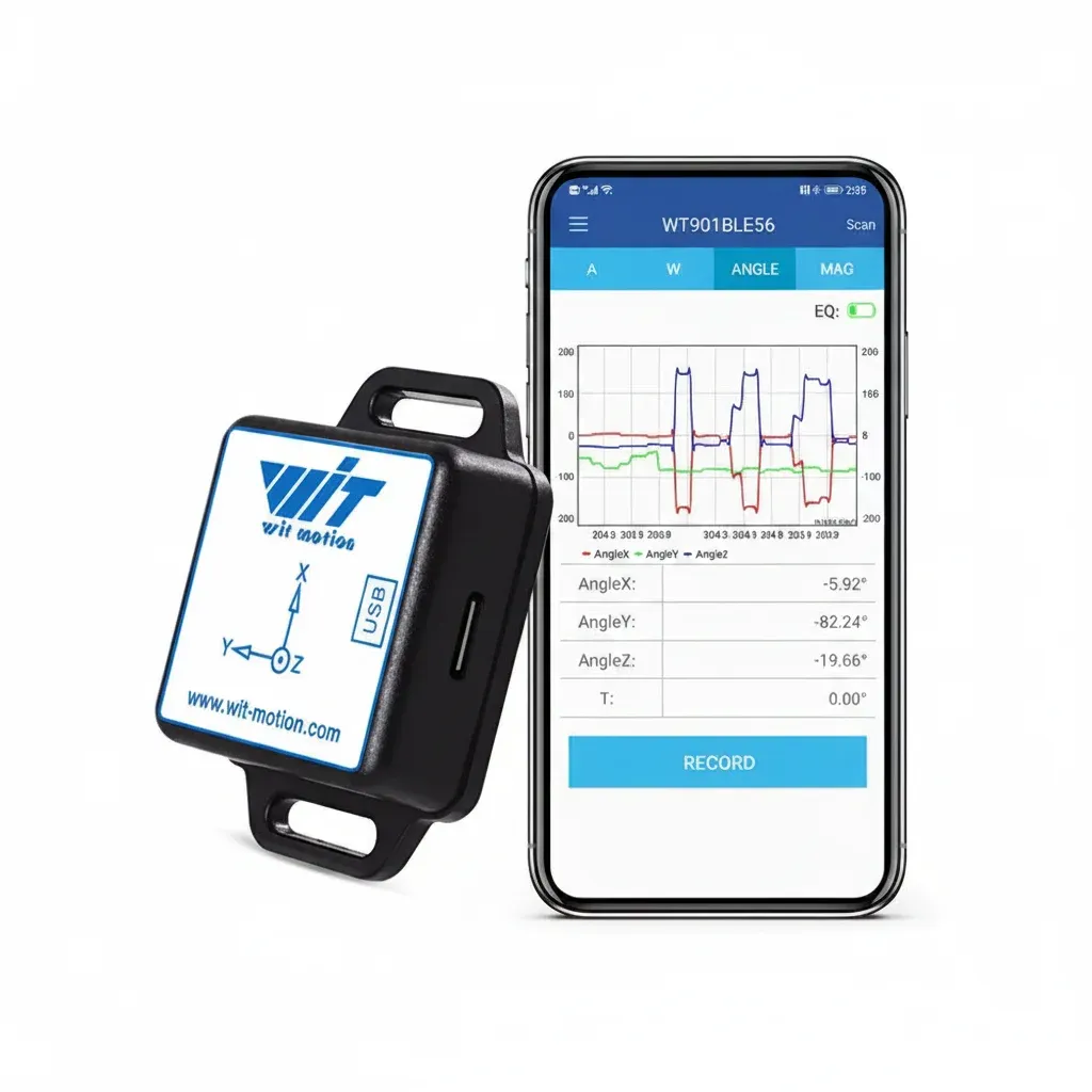
The WitMotion Bluetooth 5.0 nine-axis family combines acceleration, angular-rate and magnetic-field sensing with onboard dynamic Kalman fusion. Manufacturer documentation lists configurable output up to 200 Hz. That number is a maximum setting, not a promise that every chosen output, receiver and radio environment will deliver a gap-free 200 samples each second. Measure effective timestamps and packet continuity in your own setup.
The current site listing is £117.04 for the WitMotion Bluetooth IMU. Before spending that on a workshop project, confirm that the protocol, required software and mounting arrangement fit your computer and method. It is not presented here as a navigation-grade reference or a substitute for traceable calibration.
Frequently asked questions
Is gyroscopic precession the same as gyroscope drift?
No. Precession is a physical change in the direction of a spinning body's axis under torque. Gyroscope drift is an accumulating estimate error caused by bias, noise, temperature and integration.
Can a MEMS sensor measure a spinning top's precession?
It can measure the angular-rate components produced by the motion if it is mounted securely and its range and sample timing suit the experiment. It does not measure precession as a separate magic output.
Why does a faster-spinning top precess more slowly?
In the steady, fast-spin approximation, greater spin creates greater angular momentum. The same torque then changes its direction more slowly, so the precession rate falls.
Do I need a magnetometer for a precession experiment?
Not always. A gyroscope can capture short-duration rotation rates, while an accelerometer can help with tilt. A magnetometer adds a heading reference but may be distorted by steel benches, motors and magnets.
Check the sensor against your method
Compare the documented outputs, protocol and maximum update setting with the measurements your workshop experiment actually needs.
View the current product page — £117.04Fact basis: OpenStax University Physics on torque-induced precession; MIT OpenCourseWare classical mechanics; WitMotion WT901 BLE/SDCL product documentation and BLE 5.0 protocol. Product suitability remains application-specific.