IMU Sensor Guide for Robotics Projects
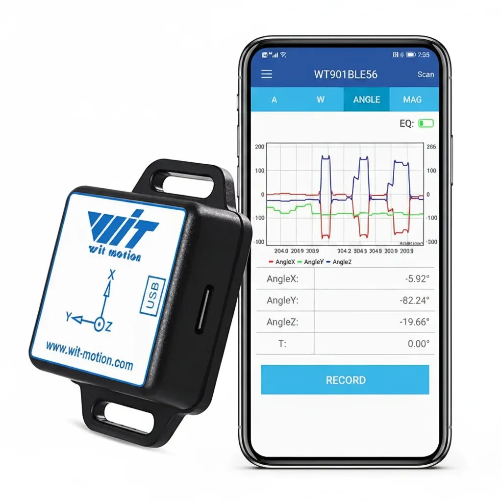
6-axis versus 9-axis IMU sensor data
An inertial measurement unit combines motion sensors in one package. A six-axis IMU has a three-axis accelerometer and a three-axis gyroscope. A nine-axis IMU adds a three-axis magnetometer. “Nine-axis” describes nine measurement channels; it does not give a rigid robot nine mechanical degrees of freedom.
| Data | What it contributes | Main limitation |
|---|---|---|
| Acceleration, X/Y/Z | Linear acceleration; gravity direction when other acceleration is modest | Motor vibration and vehicle acceleration can be confused with tilt |
| Angular rate, X/Y/Z | Fast changes in roll, pitch and yaw | Bias accumulates when rate is integrated into angle |
| Magnetic field, X/Y/Z | A possible reference for heading relative to the local field | Motors, steel and current-carrying wires distort the field |
For a wheeled robot that needs short-term pitch and turn-rate feedback, six-axis data may be sufficient. If the project needs heading relative to the local magnetic field, nine-axis data offers another reference, but only after hard-iron and soft-iron effects have been considered in the assembled robot.
Raw measurements and onboard sensor fusion
Raw acceleration and angular-rate readings are the evidence closest to the sensors. Fused Euler angles or quaternions are estimates produced by a filter. They are convenient for ROS visualisation or a Python prototype, but they embed assumptions about gravity, noise, magnetic conditions and motion.
A quaternion avoids the singularity associated with particular Euler-angle sequences, yet it is not automatically accurate. A poor magnetic reference, wrong axis convention or unrecorded filter setting can produce a confident-looking orientation that is wrong.
If you only need angular-rate behaviour and drift diagnosis, the more focused gyroscope sensor guide explains range, output rate and independent logging.
A practical IMU selection checklist
- Define the observable. Write down whether the code needs raw angular rate, tilt, quaternion, magnetic heading, vibration or all of them.
- Estimate the fastest motion. Select a range that leaves headroom without discarding useful resolution. Confirm it in a controlled prototype log.
- Set a timing budget. Output rate, sensor bandwidth, interface latency and software scheduling are separate. A configured figure is not proof of complete end-to-end delivery.
- Choose the integration route. Decide whether Bluetooth is for setup and logging, or whether the robot needs a wired interface. Check the exact protocol and operating-system support before ordering.
- Check electrical compatibility. Verify supply voltage, signal levels and connector pinout against the current manual and your controller. Do not rely on a marketplace title.
- Plan the mount. Keep the axes known, the fixing rigid and the device away from motors, magnets and high-current cables where practical.
- Inspect documentation early. Download the manual, protocol and example code while there is still time to change the design.
Integrating an IMU before a university deadline
Begin with a stationary table test, not the complete robot. Capture the device identity, firmware if exposed, configured range, output content and rate in the project log. Rotate each axis by hand and verify signs. Only then transform measurements into the robot or ROS coordinate convention.
Next, test repeatability. Power-cycle the device, repeat the same known orientation sequence and compare the start-up estimate and bias. Keep the raw files with configuration notes. This is stronger evidence than one polished plot, and it makes late faults easier to trace.
The WitMotion Bluetooth 5.0 nine-axis unit listed here outputs three-axis acceleration, angular velocity and magnetic field, plus attitude and quaternion data. Its documentation describes onboard dynamic Kalman fusion and a maximum configurable output rate of 200 Hz. The official WitMotion BLE 5.0 code repository provides examples for selected desktop and mobile languages. Arduino examples published for other WitMotion interfaces do not prove compatibility with this BLE model, so confirm the exact repository, protocol and firmware before basing a submission on it.
For Python or ROS, a serial or Bluetooth transport working on one laptop is only the first milestone. Add reconnection handling, packet validation, timestamps, unit conversions and a recorded configuration. If the project is safety-related, a wireless link and example driver are not evidence of deterministic control timing.
Limits to state clearly in the report
No position from an IMU alone: integrating acceleration twice makes small bias and attitude errors grow rapidly. An IMU supports dead reckoning; it does not provide bounded long-term position without external observations.
No universal magnetic heading accuracy: local field distortion depends on the finished robot and its operating environment.
No guaranteed real-time rate from a headline maximum: the effective rate depends on configuration, selected outputs, link quality, receiver and logger.
The current site listing for the WitMotion Bluetooth 5.0 nine-axis IMU is £117.04. It can reduce packaging and fusion work for a time-limited prototype, but suitability still depends on the current manual, interface, physical installation and the evidence standard required by your course or application.
Frequently asked questions
What is the difference between a 6-axis and 9-axis IMU?
A 6-axis IMU combines three accelerometer axes and three gyroscope axes. A 9-axis IMU adds a three-axis magnetometer, providing a magnetic-field reference that can assist heading but is vulnerable to local interference.
Does a 9-axis IMU have nine degrees of freedom?
Not in the strict mechanical sense. Nine-axis usually counts nine sensor channels: three acceleration, three angular-rate and three magnetic-field axes. A rigid body still has six mechanical degrees of freedom.
Should a student robotics project use raw or fused IMU data?
Log both when possible. Fused attitude is faster to integrate into a demo, while raw timestamped data lets you diagnose mounting, bias, vibration and filter assumptions when the result is wrong.
Is Bluetooth suitable for a robot's control loop?
Bluetooth can be convenient for configuration, monitoring and non-critical logging. Do not assume deterministic latency or packet delivery for a safety-critical control loop; validate the complete link or use an interface designed for the timing requirement.
Match the IMU to your evidence plan
Review the available raw outputs, fused data and protocol before freezing the mechanical and software design.
View the current product page — £117.04Fact basis: Advanced Navigation's IMU introduction for inertial-sensor fundamentals; WitMotion product, BLE 5.0 protocol and public code documentation for outputs, onboard filtering and maximum configuration. Compatibility and accuracy remain model-, firmware- and project-specific.